3.3.1. Rules for drawing roads and road sections
- 3.3.1.1. Drawing rules for whole road networks
- 3.3.1.2. Rules for drawing roads in one/two arcs (one or two lines)
- 3.3.1.3. Rules for drawing straight and curved road sections and turns
- 3.3.1.4. Rules for drawing u-turns with two lines
- 3.3.1.5. Rules for drawing intersections
- 3.3.1.6. Drawing rules for sidewalks, pedestrian paths, and bike paths
- 3.3.1.7. Rules for drawing seasonal roads
Alert
Be careful when drawing roads. The road network is used to set routes, so drawing errors can lead to routing mistakes.
Techniques for drawing and editing road sections are similar to the techniques for drawing and editing all linear items on YME.
For their descriptions, see 2.6.1.1. Simple linear items: drawing techniques, 2.6.1.2. Simple linear items: editing techniques.
There is a tool for drawing circular road sections.
When you draw a road section, keep in mind that certain drawing rules relate to features of the road in question (rather than to that particular road section). For example, some roads are drawn with a single line and others with two lines (for more information, see Section 3.3.1.2. Rules for drawing roads in one/two arcs (one or two lines)).
This is why the drawing rules for sections of road include:
-
Drawing rules for roads and whole road networks:
-
Drawing rules for sections of road:
When drawing road elements, the points where the road elements intersect (the start or end point of each element) form independent objects of type Intersection
. Intersections are created automatically when you draw road sections and may be used to edit the shape of the road network (for more information, see section 2.9. Intersections) and when adding road signs, traffic lights, and speed cameras.
When drawing roads, do not create road sections and their intersection boundaries excessively. The start and end points of road sections must overlap:
-
— With intersections
-
— With points where road section attributes change their values (such as changes in speed limits, or a road section passing the boundary of another traffic installation like a bridge or a tunnel, etc.)
-
— With points where a road section passes a boarder of another country (see section 3.3.1.1.7) or locality (see section 3.3.1.1.9)
-
— With a number of Places, such as:
3.3.1.1. Drawing rules for whole road networks
3.3.1.1.1
Road networks should be connected: all fragments of a road network that forms in a given area should be connected on the map. For example:
|
Correct |
Incorrect |
|
|
|
In a connected road graph, road sections are connected both geographically and in terms of attributes, which means various types of vehicles are able to use them.
If a certain type of vehicle can't get to or leave a road network section which it is not located in a large restricted area or an isolated terrain item, this section is considered excluded from the connected road network and requires editing its geography or attributes.
Note
Pedestrian road sections that are inaccessible to bicycles are not excluded from bicycle routing and are not considered isolated.
If you can only get to a certain isolated
road section by railroad or ferry crossing (but not by motorway), then the road network should include these railroad and ferry crossings, and you should add attributes to them accordingly (see Section 3.3.2.6. Type of structure).
Roads that are under construction can be connected to the road network via lower-class roads (see 3.3.2.13).
Note
Road sections with timed maneuver restrictions are not considered to be isolated from the road network.
When extending roads in areas where the road network is shifted relative to the satellite image, it's preferable to align existing roads with the satellite image, but it's not required to do so. In this case, new sections should be drawn with approximately the same shift as the road network at that location.
3.3.1.1.2
When you draw the road network, make sure that you don't overlap different road sections, draw a section that intersects with itself, or duplicate road sections:
|
Correct |
Incorrect |
|
|
|
When you draw an item on the map, the program monitors if the drawing is correct and reports any errors to you:
But not all errors are recognized automatically.
3.3.1.1.3
When you draw bends in roads or intersections, the end points of road sections that form crossings should meet and form an intersection. There should not be any hanging points
(other than in cases where the road is blocked in that area):
|
Correct |
Incorrect |
|
|
|
Note
-
When redrawing roads, do not move
extra
lines of the road network from the roadbed. If there are service objects preventing you from removing extra lines of the road network, leave its geometric form unchanged. -
Do not move road sections located on railway platforms outside these platforms.
3.3.1.1.4
Draw the road network based on satellite images.
If the satellite image is offset relative to tracks, then the staff must adjust the roads based on track information (for example, when there is a discrepancy between the track line and the central line of the roadway, and tracks aren't located within the roadbed in the image due to the terrain).
This tool is available to employees only.
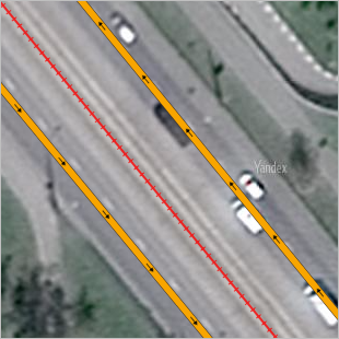
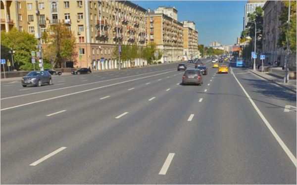
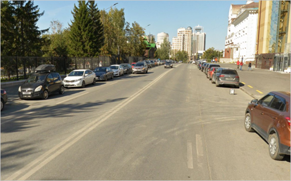
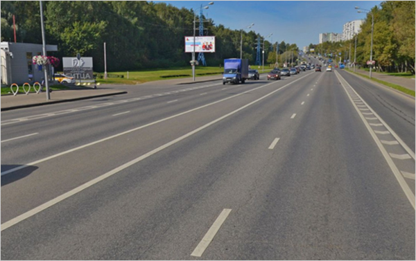
When drawing two-way roads as a single line, draw the road line along the lane marking that divides oncoming passenger car traffic. When there's no marking, use the geometric center of the roadbed.
When drawing two-lane and one-way roads, draw road lines along the geometric center of the lanes intended for traffic, including tram tracks where cars are allowed to travel (ignore taxi and public transport lanes). Roads with an even number of lanes to be considered while drawing should be drawn according to the road markings that approximately coincide with the geometric center of the lanes.
If a road section passes through a railway platform, draw it using its geometric center.
You shouldn't shift the road line for turnouts or additional lanes for turning before intersections.
Note
In cases where road sections intersect with 3D building models, the employees may shift these sections from the center of the roadbed or the markings described above, but can't move them beyond the boundaries of the roadway itself.
When you draw road sections that go over bridges, pay attention to the displacement of the bridge on the satellite image (for more information, see Section 2.3.1.4. Bridges).
If the images are significantly displaced from the tracks, don't manually edit the geometry of the road network, instead reporting the large-scale shift using the feedback form.
3.3.1.1.4.1
If the road markings designating the number of lanes on a road have partially worn away due to weather conditions or over time, determine the number of lanes and the correct way to draw the road (in one or two lines) based on data where the last applied markings are visible.
An exception to this rule concerns maneuvers that were prohibited only by markings. For example, if the most recent source shows that a maneuver is already permitted by road markings, don't draw the prohibited maneuver (or remove it).
If the most current data source shows that only some markings on the road have been updated while part of the markings remain unchanged (even if partially worn away), then the old markings are considered to also be in effect, provided that the new markings don't contradict the old ones but rather supplement them.
If you determined that a specific road marking element was deliberately erased, don't take it into account.
3.3.1.1.5
When drawing and attributing the road network, take into account the actual possibility of passage/travel along the road sections.
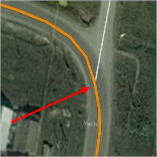
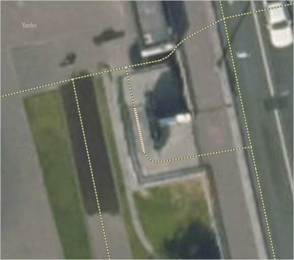
If a previously existing motorway has become physically impassable, don't draw it. If the road still allows pedestrian access, draw it as a pedestrian road.
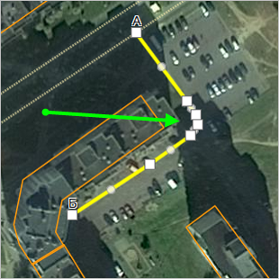
Examples
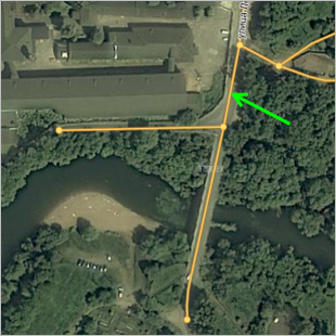
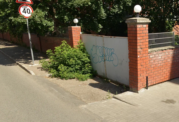
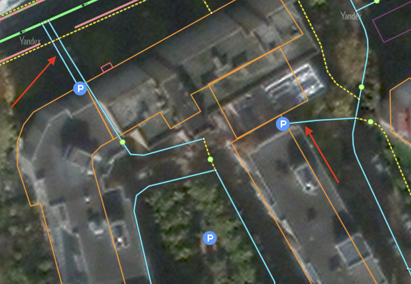
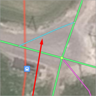
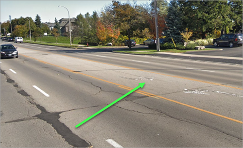
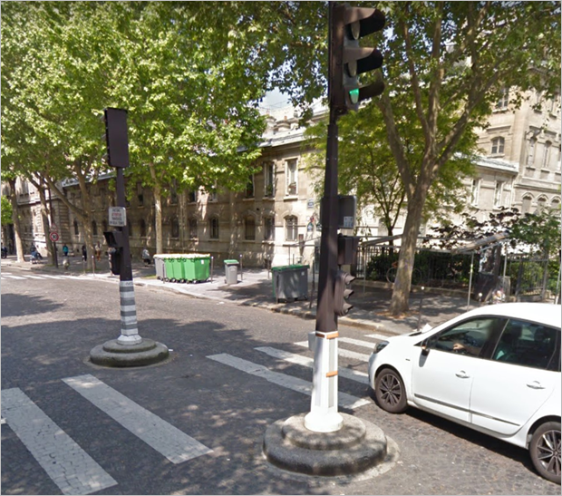
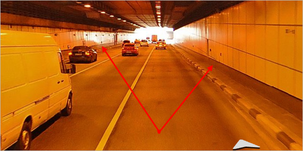
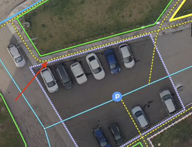
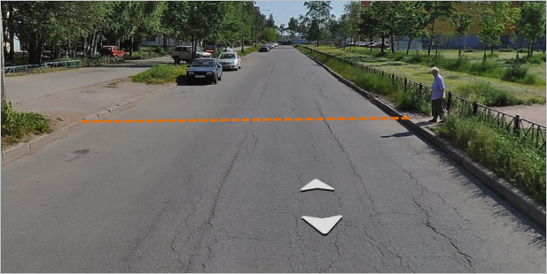
-
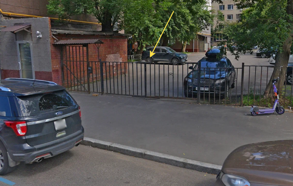
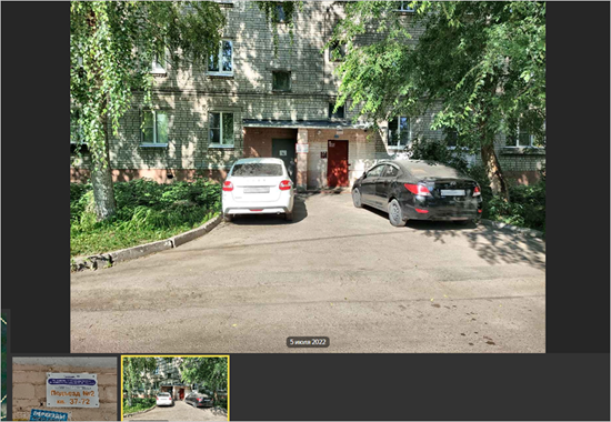
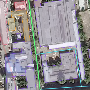
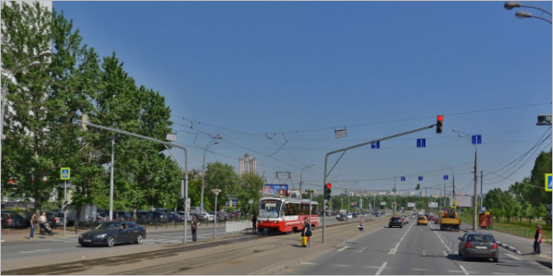
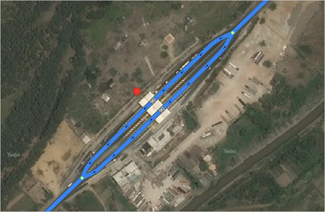
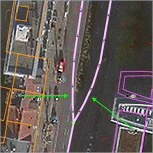
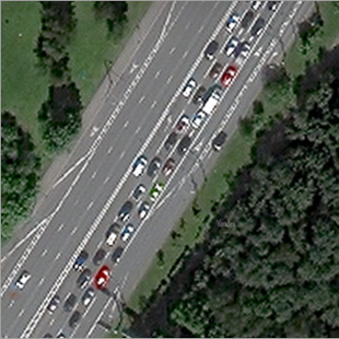
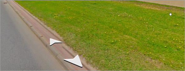
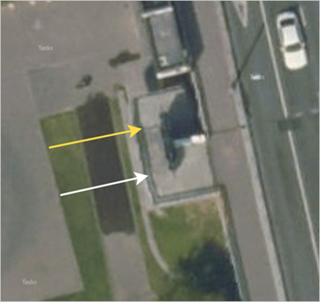
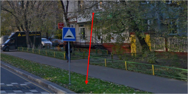
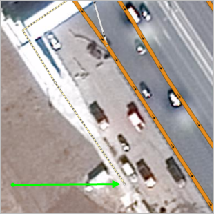
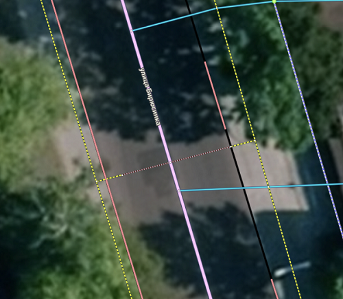
Previously, vehicle access to the adjacent area was possible, as evidenced by the gates still present on site (yellow arrow). But the curb indicates that vehicle access is no longer possible. This is why, on the map, this road is marked as a pedestrian road, and the "Restricted entry" rule is added at the gate location.
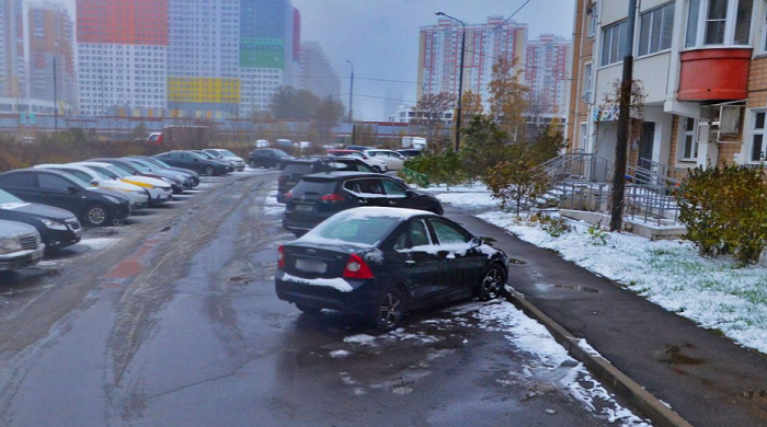
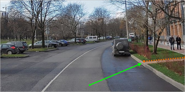
-
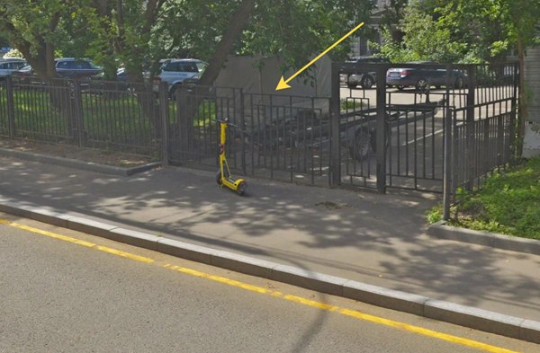
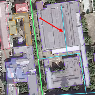
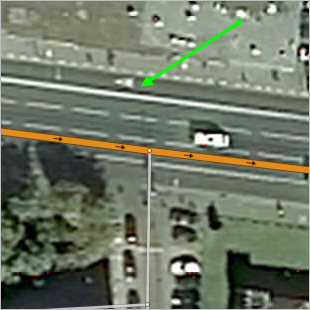
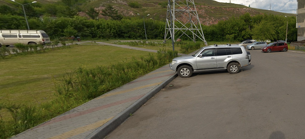
Vehicle access to the adjacent area is possible because there's no curb. Bushes in front of the gate indicate that this entrance is not used often and is therefore a service or emergency entrance. Draw this road as a motorway on the map and add a service entrance to the area at the gate location (for more information on creating service entrances to areas, see point 3.3.4.2.5 of section 3.3.4.2. Drawing rules).
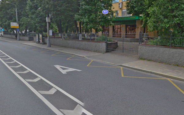
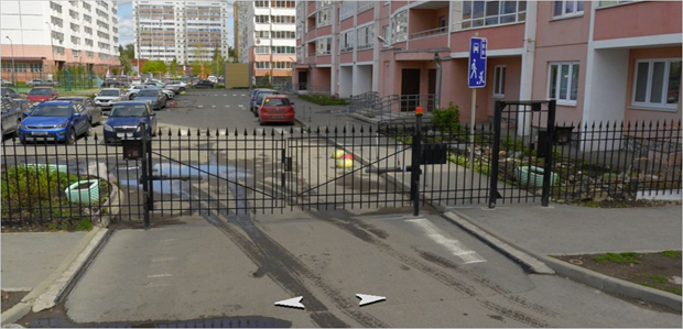
-
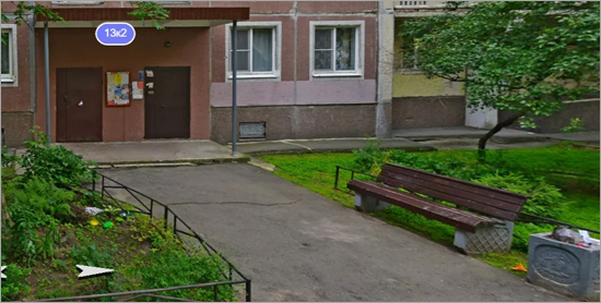
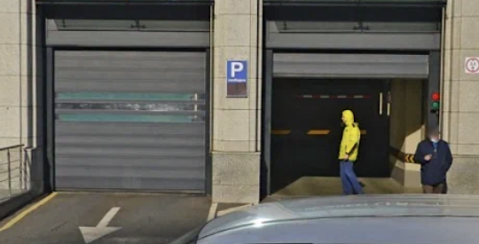
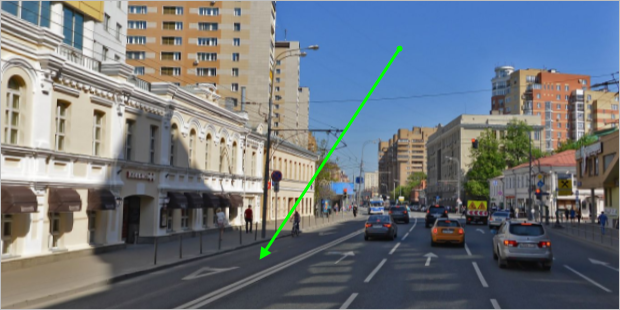
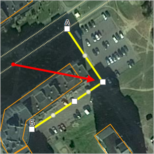
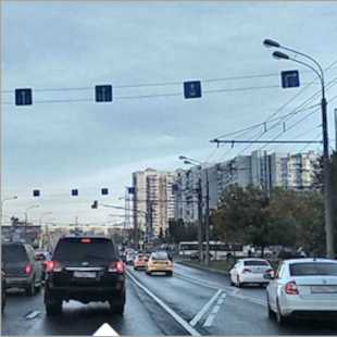
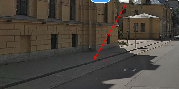
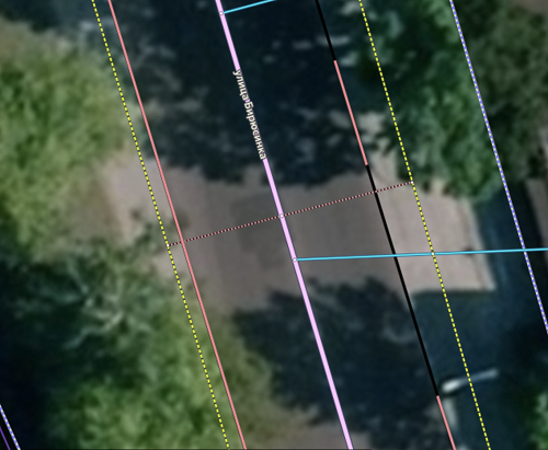
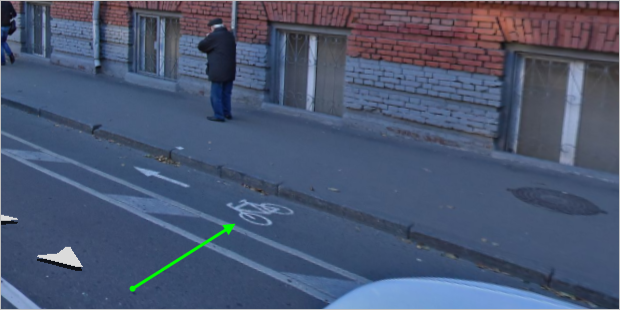
Despite the lowered curb for vehicle access, a public transport lane has appeared in the area, so passenger cars can no longer enter the courtyard at this location. The road is shown as pedestrian with "Restricted entry" at the location of the gate.
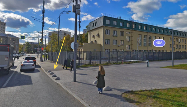
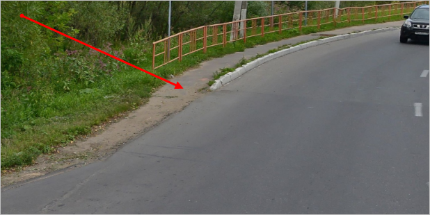
-
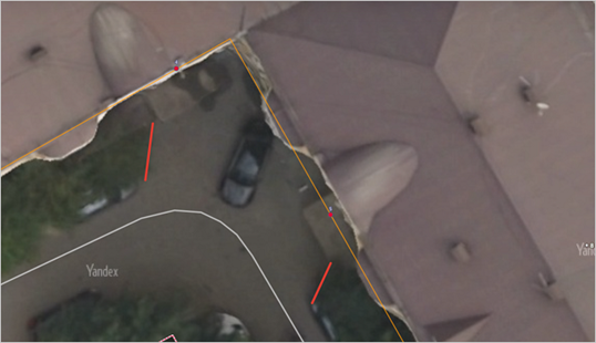
Concrete hemispheres are placed along the actual curb line, making it impossible to drive on the road. Don't draw the road.
3.3.1.1.6
You don't have to include certain minor details in your drawing of the road network.
Don't:
-
Draw driveways to private houses located on the first development line relative to the main road.
Correct
Incorrect

-
Draw roads that pass through private plots to houses located within blocks, on the second development line relative to the main road.
Note
If you can't determine whether a building is private, apartment, or occupied by one or multiple organizations, don't draw a driveway to this building.
You may:
-
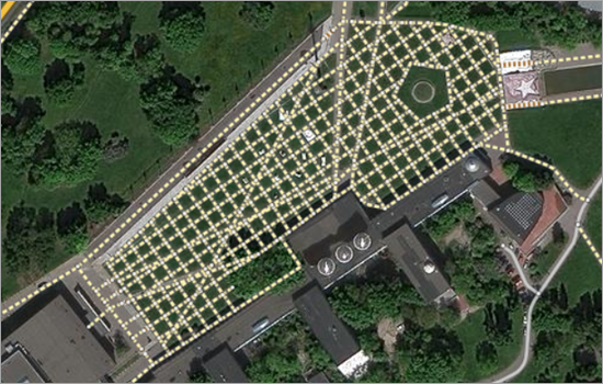
Draw class 10 paved paths located within parks and squares that form a regularly-shaped pattern. For such cases, you should fully draw the whole path network. For example:
-
Draw paved pedestrian paths in urban areas that are physically distinguished from the surrounding area (including paths to entrances from intra-block driveways):
Note
Pedestrian paths between adjacent entrances are considered to be physically distinguished from the surrounding area if they are separated from each other.
The courtyard passage extension below isn't considered to be a distinguished path:
When mapping paths to apartment building entrances, you can draw them to the entrance itself, to the steps, to the porch, or to other similar items. The most correct approach is to draw them to the entrance steps. In this case, the steps themselves should stop before the entrance canopy or structure:
-
Draw roads that pass through public (not private) plots and lead to residential buildings located within blocks, on the second line relative to the main road even if they have a barrier and/or pass through an arch:
-
Draw pedestrian paths leading to organizations that have indoor maps and are accessible, among other ways, from outside the building (don't draw paths to staff entrances, as this is considered excessive).
3.3.1.1.7
Only draw roads leading to roofs for buildings that belong to the utility and storage
or Stylobate
type.
Only draw roads in underground and multi-level parking lots in the following cases:
-
The parking area is located under a shopping or business center or there are no buildings above the parking area.
-
The public parking area is located in a
utility and storage
building, and the road doesn't lead outside the premises (in such cases, the minimum number of roads connecting all entrances and exits to the building can be drawn):Correct
Incorrect
-
The one-way entrance and exit from the underground parking are located in close proximity to each other (in this case, the entrance and exit sections should be connected in an arc within the structure without leading them deep into the building):
To ensure connectivity between roads on one-way entrances to and exits from underground parking lots, set the traffic to A ⇆ B if the roads are not located close to each other and cut off near a building's polygon.
3.3.1.1.8
Road sections that cross country borders are cut at the point of crossing. The crossing is marked as an Road intersection:
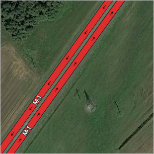
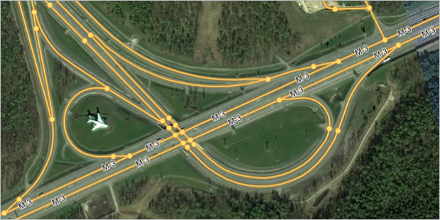
Motorways that pass through several countries (which are usually Numbered highways, such as M-1 Belarus or M-2 Crimea), are cut at crossings into sections running through different territories (also see Section 3.3.3.1.1).
This allows you to link the road to the administrative division (country) where it is located. The road will be divided into fragments that correspond to the territories of the different countries that it runs through:
3.3.1.1.9
Outside regular development blocks, vegetation items may be crossed by railways or single-lane motorways and pedestrian roads.
Within regular development territories, vegetation items may be crossed by single-lane motorways and pedestrian roads that pass through their territory, provided these roads belong to one of the following classes:
- 10 (Pedestrian and bike paths).
- 9 (Field and forest roads).
- 8 (Driveways).
- 7 (Roads of minimal significance) accessible only to pedestrians and/or bicyclists.
Vegetation items of the Park, square
, Nature reserve
, and Cemetery
types (both within and outside blocks of regular development) may be crossed by single-lane motorways and pedestrian roads of any class, provided these roads serve as entrances to or exits from the area, or as through-routes across the vegetation item's territory.
See also point 3.9.1.5.
3.3.1.1.10
When you draw roads that intersect with locality borders, you must split the border at the intersection point (creating two road sections).
Note
Streets linked to a locality should be located entirely within the borders of that locality. See section 3.3.1.4.
3.3.1.1.11
Don't change the main road's shape if you're drawing the road expanding and getting new lanes near toll booths and border checkpoints. Checkpoint passages don't need dedicated lanes.
In addition, don't use separate sections to draw widening roads at entrances to shopping malls, airports, and other facilities if entering or remaining on these premises requires subsequent payment.
Correct:
Incorrect:
3.3.1.1.12
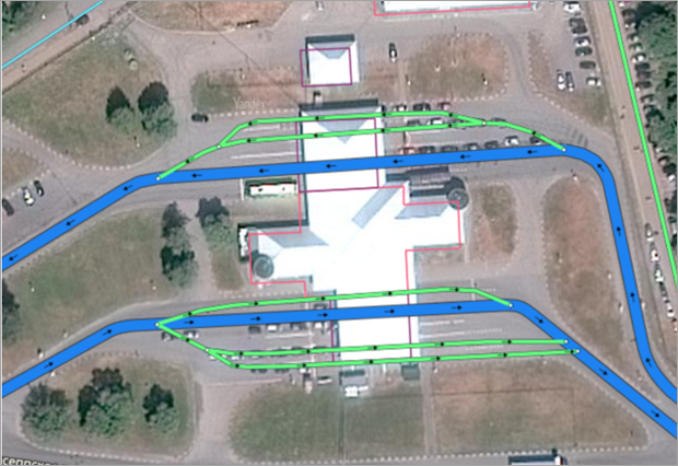
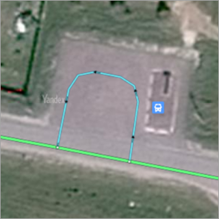
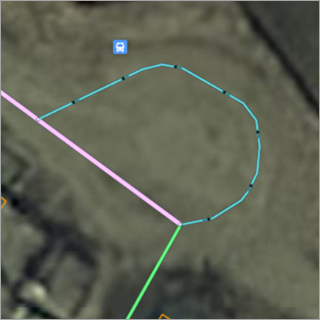
Draw a U-turn site for public transport along the site's perimeter using the line of a class 8 road, which is one-way in the direction of public transport movement and accessible only to public transport in the following cases:
- The u-turn site is separated from the main roadway by marking.
- The u-turn site largely extends the roadway and includes a stop or parking area for public transport.
|
Correct |
Incorrect |
|
|
|
|
|
|
3.3.1.1.13
Areas leading to filling stations should be drawn using class 8 road sections, even if they aren't separated from the main road by barriers or markings.
3.3.1.1.14
When drawing or editing edges of the road network, you should also create or edit maneuvers in cases regulated by 3.3.4. Road signs
3.3.1.1.15
If a reconstruction or change in the traffic pattern renders a road section inaccessible (due to a physical obstacle, signs, or road marking), such a section should be marked with the attribute Under construction.
3.3.1.1.16
When drawing road sections that pass through Road structures, the recommended practice is to draw these structures as well.
3.3.1.1.17
In certain areas, the boundaries of road sections on bridges or in tunnels, and the boundaries of sections with transition levels are aligned with the boundaries of highly detailed roadbeds (HD roadbeds). If you need to edit something in such areas, newly created or edited road sections should also align with the boundaries of HD roadbeds. Align simultaneously with editing or creating a road section.
Only certain employees can edit such items.
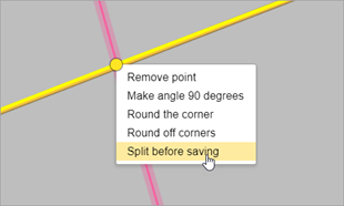
Example 1
If you need to move an intersection point of two roads onto a roadbed with transition levels (0-1), then edit the road section, not the intersection point. When redrawing a road section, draw the point at the border of the roadbed and select the "Split before saving" option for this point. After redrawing, correct the maneuvers that may have changed their geometry due to the change in the intersection point.
Example 2
If you need the road intersection point to be located before the beginning of the roadbed with transition levels (0-1), then follow the previous example and edit the road section, not the intersection point. Don't draw new road sections. After redrawing, correct the maneuvers that may have changed their geometry due to the change in the intersection point.
3.3.1.2. Rules for drawing roads in one/two arcs (one or two lines)
There are two ways to draw roads in Yandex Map Editor:
-
In one line — for both one-way and two-way roads:
-
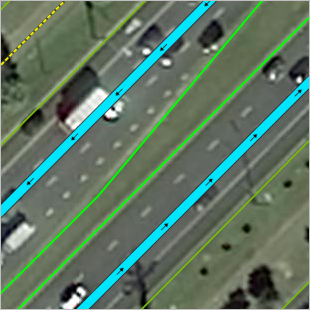
In two lines (one representing each traffic direction):
3.3.1.2.1. Drawing in two lines
In some cases, it is mandatory to draw roads in two lines, while in other cases, it is preferable but not mandatory.
3.3.1.2.1.1. When it's mandatory to draw in two lines
-
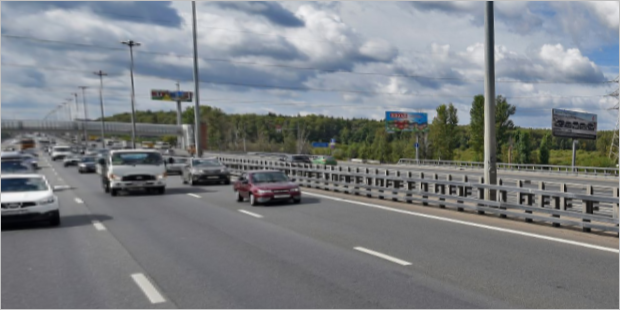
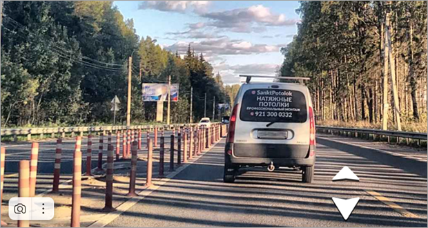
Drawing in two lines is mandatory when there's a physical divider on the road.
A barrier or dividing road posts
Lawn, flowerbed
Tram tracks vehicles can't or aren't permitted to drive to (elevated above the road or separated by a solid line)
3.3.1.2.1.2. When it's preferred to draw in two lines
-
It's preferred to draw roads in two lines in the following cases:
When the road is a class 1 (expressway)
When the road has three or more traffic lanes in one direction
When the road has a double solid line and two or more traffic lanes in each direction available to passenger vehicles.
When the road has an element that separates oncoming traffic lanes from each other if it stands out physically and/or using road markings and separates adjacent roadways and road sections not intended for traffic or stopping vehicles.
-
Note
When drawing roads using one or two lines, consider central turning lanes (such as in the US) full-fledged traffic lanes. Example of a central turning lane:
If a two-way toll booth has the same location for both traffic directions on a road that should otherwise be drawn as a single lane, split the road into two lanes near the toll booth, then converge them back into a single lane beyond the booth.
-
3.3.1.2.2. One-lane drawing
Draw all roads that don't meet the criteria for having two lanes (see 3.3.1.2.1) using one lane.
3.3.1.2.2.1
-
Don't draw additional road lanes for a marked lane of oncoming or same-direction traffic of public transport:
3.3.1.2.3
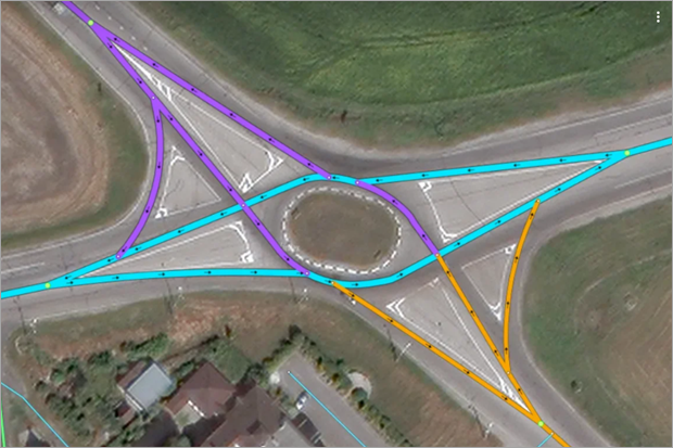
If a road has multi-level interchanges, then draw the interchanges as you would the road itself (with either one or two lanes):
3.3.1.2.4
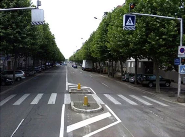
For a short section of road, you should not switch between drawing one and two lines (even if the number of lanes or the road markings change). Within localities, a section less than one block long is considered a short section.
If the road has a physical divider, draw it using two lines. An exception to this rule is cases when a pair of items that physically separate traffic lanes (forming a traffic island
at a pedestrian crossing) are positioned at a distance from each other that is less than or approximately equal to the width of the pedestrian crossing. For example, a pair of traffic lights or borders does not change the rendering of a single-lane road to a two-lane road:
You should not switch your drawing method for marked breaks in a solid double line or for a traffic island before an intersection:
Merging a two-lane road into a one-lane one should happen smoothly (otherwise the navigator may misinterpret the transition as a turn):****
|
Correct(the transition is smooth) |
Incorrect(the transition is abrupt) |
|
|
|
3.3.1.2.5
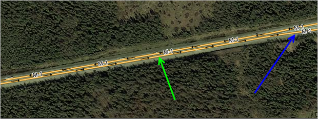
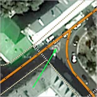
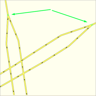
Sections of road drawn using two lines should run parallel to each other if they are parallel in reality (green arrow on the drawing). Areas where the road narrows or widens are an exception to this rule (blue arrow on the drawing):
3.3.1.3. Rules for drawing straight and curved road sections and turns
Rules for drawing straight and curved road sections (these rules supplement the general rules for drawing linear items):
3.3.1.3.1. Drawing straight sections of road
Straight sections of road should not have intermediate vertexes:
|
Correct |
Incorrect |
|
|
|
3.3.1.3.2. Drawing curved sections of road
On curved sections of road, the number of vertexes should be sufficient so that angles at slight turns are not noticeable on maps at scale 18. You should not draw more points than are necessary to fulfill this requirement:
|
Correct |
Incorrect |
|
|
|
|
|
Note
Pedestrian roads should be drawn preserving their actual geometry: you may draw unsmoothed angles if this is consistent with the road's actual geometry (for example, its boundaries are marked with a curb).
3.3.1.3.3. Drawing turns
Draw turns so they look smooth (with no angles) when viewed on a map at scale 18.
You should not draw more points than are necessary to fulfill this requirement (usually three points suffices):
|
Correct |
Incorrect |
|
|
|
To draw a smooth turn on a road, you can use the round corners tool or command.
Alert
If the turn is part of a T formation at an intersection, adhere to the rules for drawing these types of intersections (see point 3.3.1.5.4).
Also see Section 2.10.2. Map item: related edits.
3.3.1.4. Rules for drawing u-turns with two lines
If a road drawn using two lines has a u-turn:
3.3.1.4.1
Draw a two-way u-turn in fragments that run perpendicular to the lanes you drew on the road.
If the u-turn lanes are separated from one another (by a barrier, median, lawn, or traffic island entered as markup), then draw the u-turn using two lines:
|
|
|
3.3.1.4.2
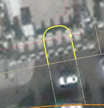
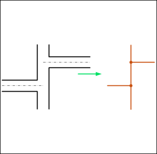
Draw one-way u-turns as arcs and indicate the traffic direction:
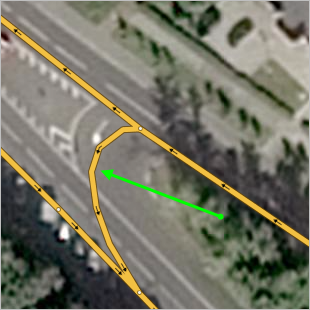
The intersection with the main road should be drawn where the dashed line turns solid.
3.3.1.4.3
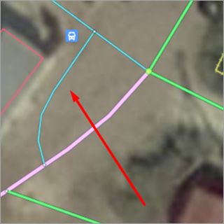
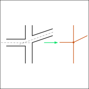
You can use a separate line of the road network to draw U-turn sections located before an intersection, provided you can't make a U-turn directly at the intersection because of the traffic rules.
In the drawing, the U-turn at the intersection is impossible due to the one-way line of the road: the direction of movement does not allow you to turn left to make a U-turn.
3.3.1.5. Rules for drawing intersections
Draw intersections to reflect the actual traffic situation there (in other words, take traffic signs, permitted turns, etc. into account regardless of if the roads that intersect there are drawn using one or two lines).
3.3.1.5.1
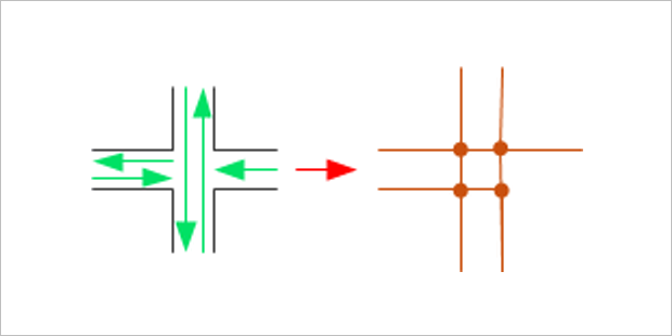
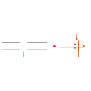
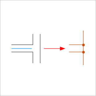
If a road intersects with two different roads that only differ by name (in other words, the driver can navigate from one to the other without performing any maneuvers), then enter one general intersection point that applies to both of them.
|
|
|
If this is not the case, then enter two intersection points
|
|
|
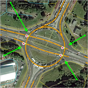
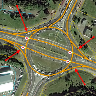
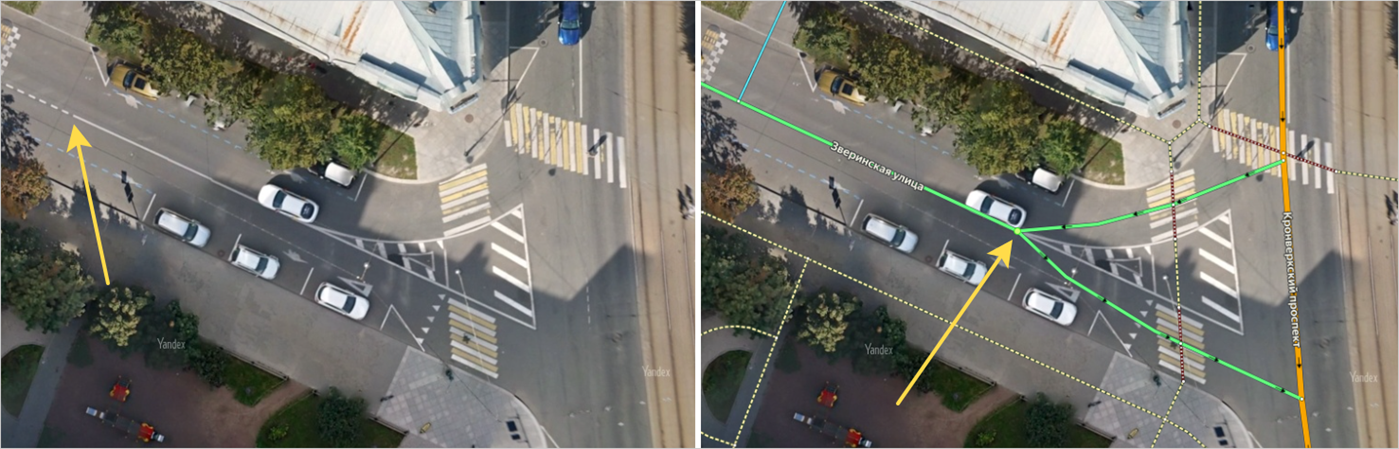
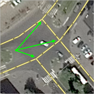
3.3.1.5.2
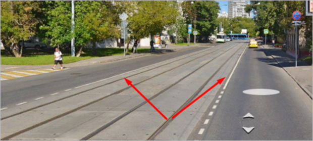
At T-shaped intersections, draw roads without excessive curvature or roundness, even if they are present at the physical location. The green arrows on the left indicate an intersection that was drawn correctly. The red arrows indicates an incorrectly drawn intersection. On the right, an incorrect drawing was corrected:
|
Correct and incorrect |
Correct |
|
|
|

This rule applies to all classes of roads, including pedestrian paths. Draw intersections where a high-class road turns and adjoins a less significant road in a similar way.
|
Correct |
Incorrect |
|
|
|
Turns are only drawn as smooth curves in cases where there is a physical divider or a corresponding marker on the map:
We recommend connecting the sections of the road network at T-junctions at right angles, but this isn't mandatory.
|
Correct drawing |
Acceptable drawing |
|
|
|
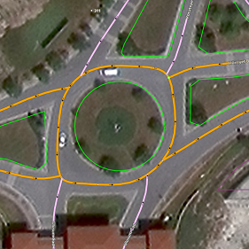
3.3.1.5.3
Circular road sections should not share intersection points:
|
Correct |
Incorrect |
|
|
|
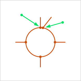
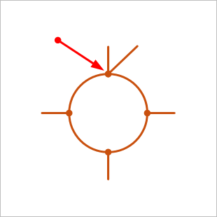
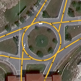
In some cases, you may need to change the geometry of sections with the Roundabout
attribute to something other than a circle to meet this rule.
|
Correct |
Incorrect |
|
|
|
3.3.1.5.4
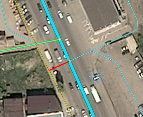
Only draw turns or exits at intersections as well as exits and lanes that run parallel to the main road as separate lanes if they're separated from the main roadway by a physical obstacle (a barrier, median, or lawn) or road markings of one of the following types:
- Traffic island.
- Solid line, bus lane, or bike lane.
- Double solid line.
Note
Don't draw exit ramps for roads that widen by one or two lanes before an intersection.
Examples of cases where you show draw an exit ramp:
|
|
|
|
|
|
|
|
|
Examples of correct and incorrect exit ramp drawing:
|
Correct |
Incorrect |
|
|
|
|
|
|
|
|
|
|
|
|
Example of a correct exit ramp drawing when there is a physical barrier:
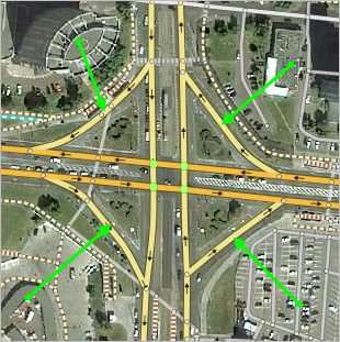
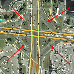
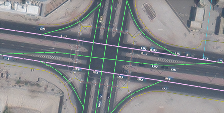
Examples of complex interchanges in the UAE that require drawing separate lines for exits:
3.3.1.5.4.1
-
Connect exits and dedicated lanes to the main road smoothly but without curvature, at an acute angle. In some cases, the road line may cross the solid line of the exit marking, but it can never cross the safety island.
Examples of correct and incorrect exit connections
Correct
Incorrect
3.3.1.5.4.2
-
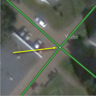
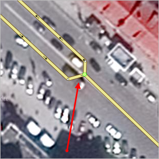
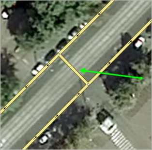
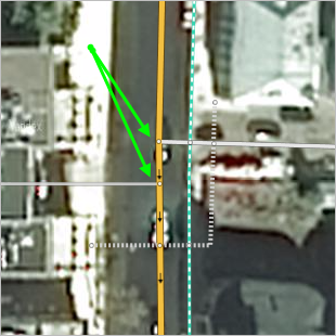
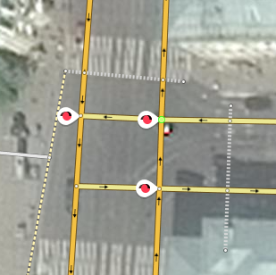
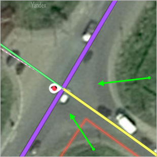
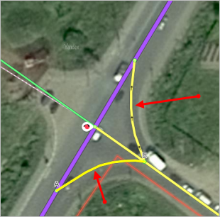
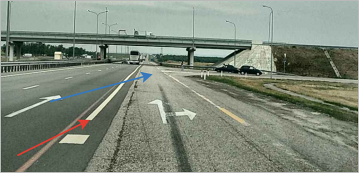
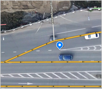
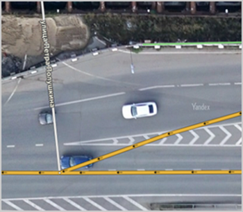
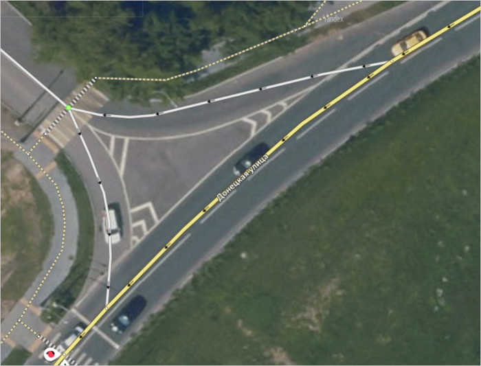
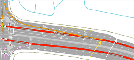
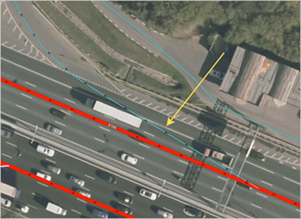
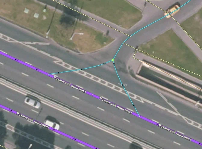
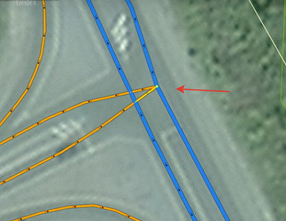
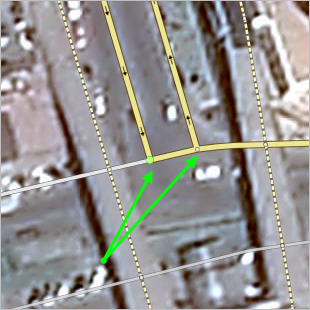
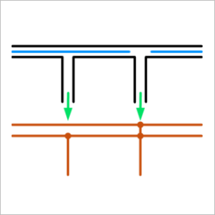
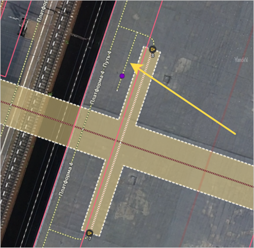
If the exit is essentially a separate lane (which means vehicles can't move in any directions other than the exit), draw the intersection with the main road at the point where the dashed line becomes solid to separate the lane vehicles can use to move in the main direction.
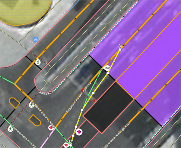
Example
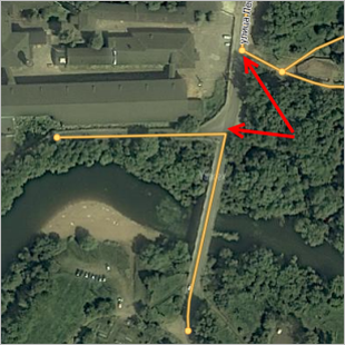
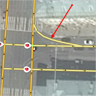
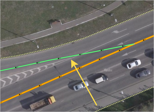
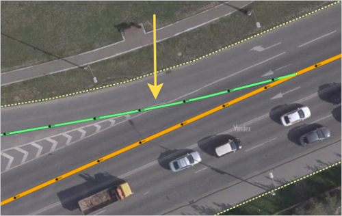
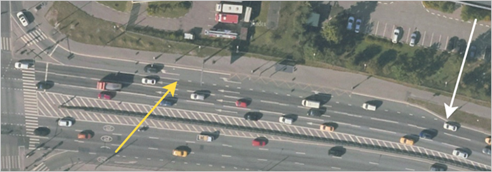
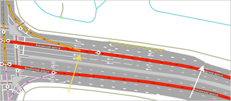
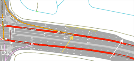
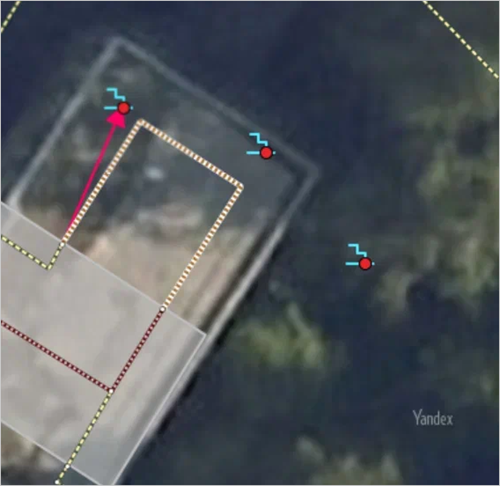
In the images below, the yellow arrow indicates the correct point to start drawing the exit:
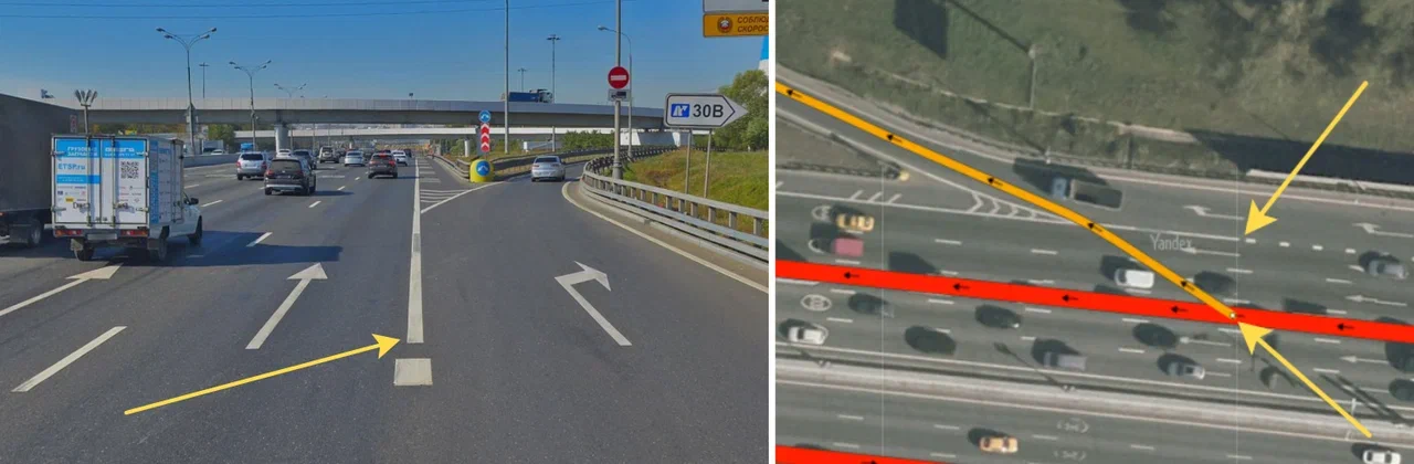
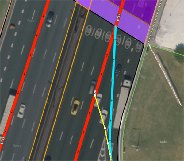
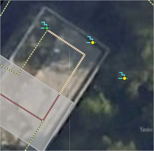
In the images below, the yellow arrow indicates the correct point to stop drawing the exit:

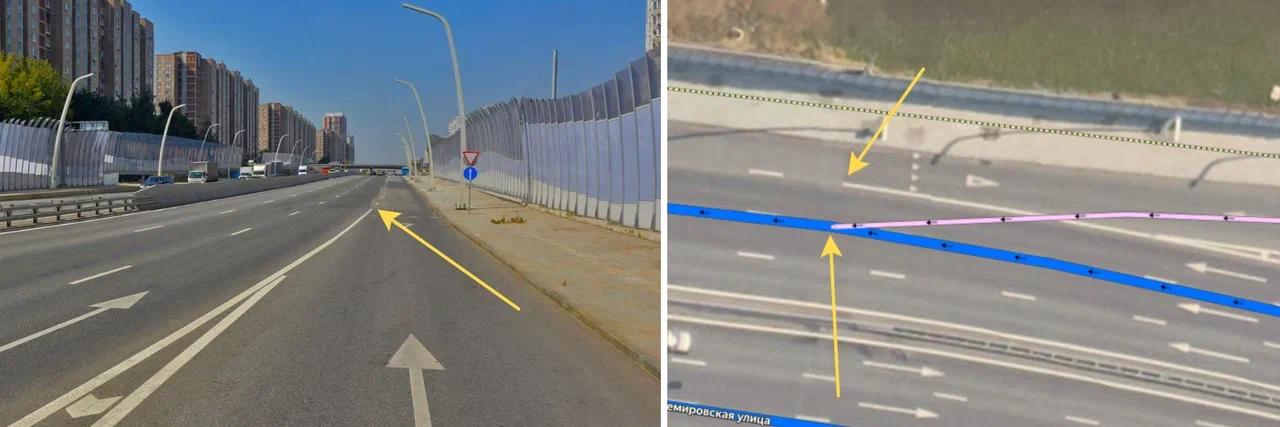
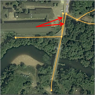
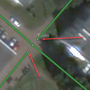
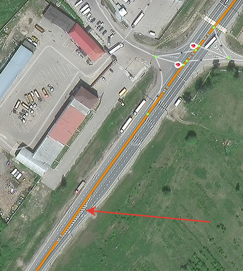
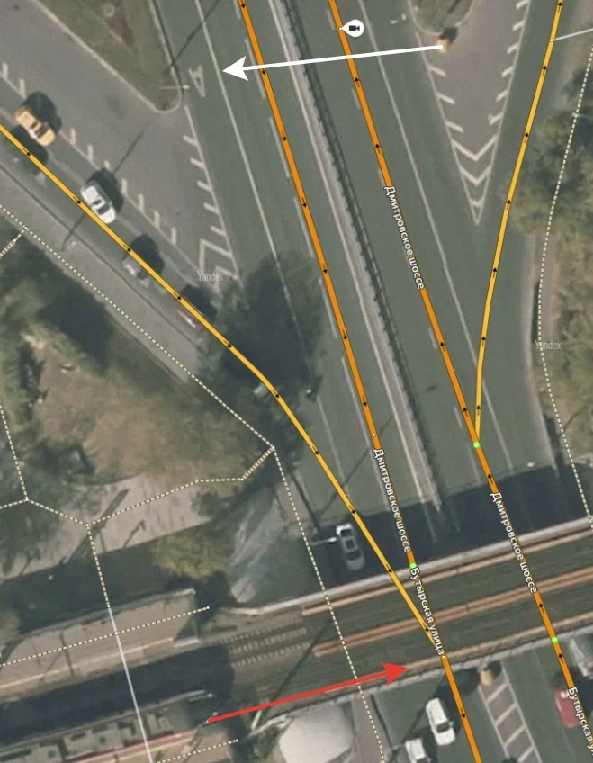
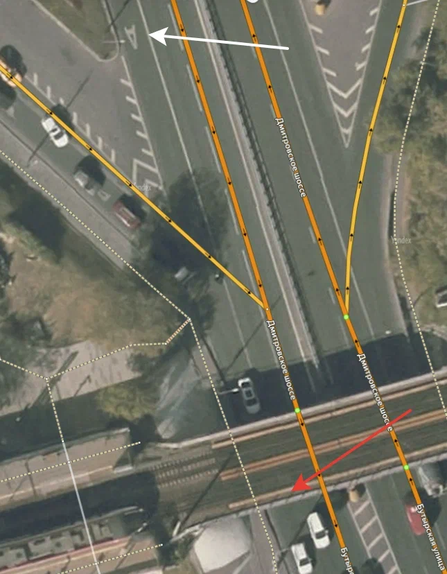
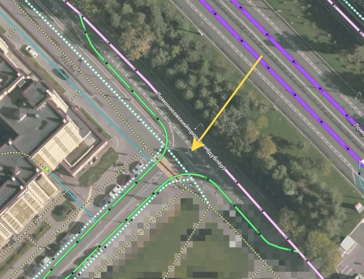
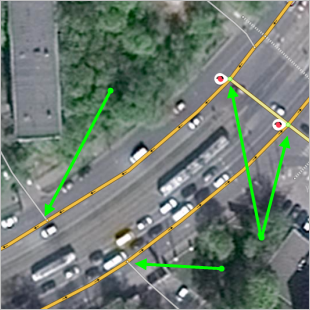
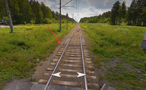
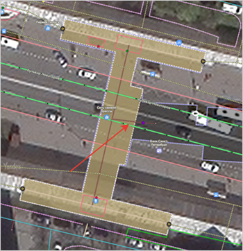
Assess the start and end points of the solid line based on where the solid line runs for all types of vehicles.
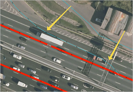
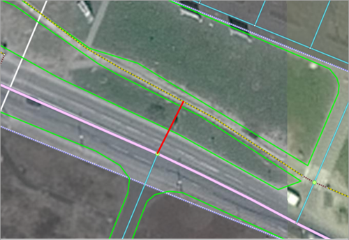
Example
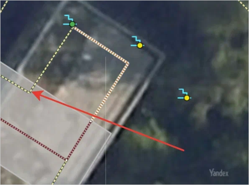
In the images below, the white arrow indicates the public transport lane, and the red arrow points to the spot where the solid line of the public transport lane ends. This is the correct point to connect the exit to the main road.
Correct
Incorrect
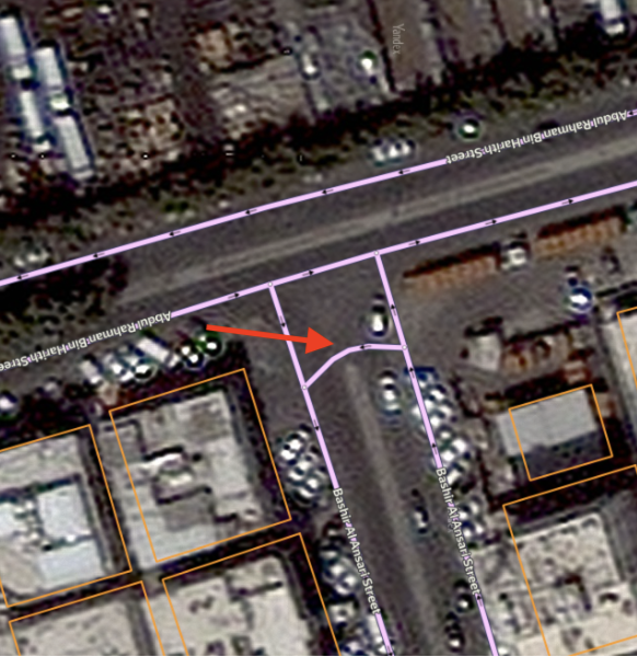
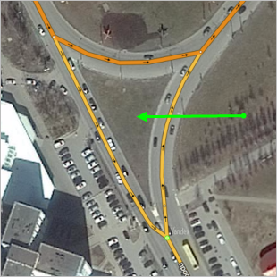
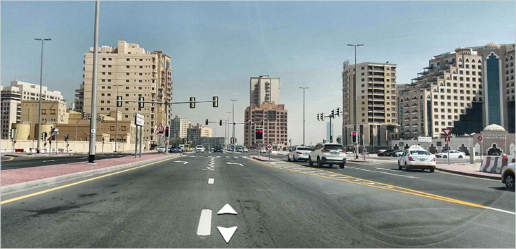
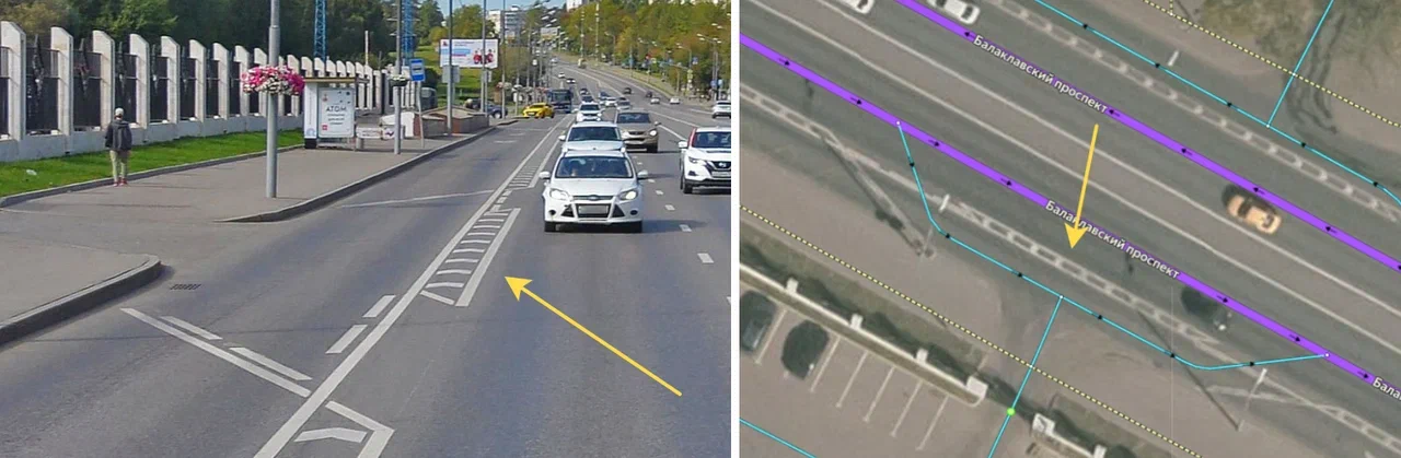
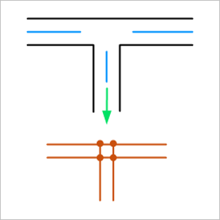
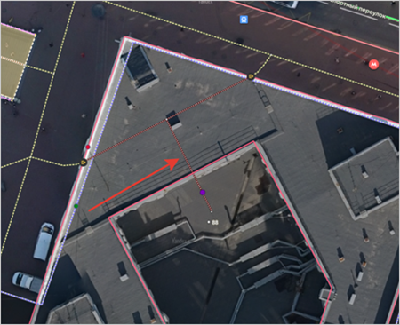
If the exit is not a separate lane (both exit and traffic on the main road are possible), the intersection with the main road is drawn at the point where the exit lane branches off from the outer lane.
Example
In the image below, the blue arrow indicates the correct point for starting to draw the exit ramp, and the red arrow points at an incorrect location:
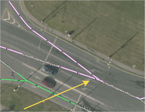
If the exit is marked only by a traffic island without solid line markings, draw it along the central line of the roadbed from the beginning of the traffic island, then connect it to the main road in as short a distance but as smoothly as possible.
Example
Correct
Incorrect
3.3.1.5.4.3
-
The rules for drawing exits described in point 3.3.1.5.4.2 are the most correct and preferable. However, you can also use the following options for drawing exits:
-
If there is a dedicated exit lane, you can connect the exit at the point where this lane appears and up to the start of the solid line that separates the exit from the road.
Example
In the image below, the yellow arrow indicates the start of the solid line for the exit and the white arrow indicates the point where the dedicated exit lane begins. The most correct and preferred option is to draw the exit from the yellow arrow, but you can also draw it anywhere between the yellow and white arrows.
Preferred
Acceptable
-
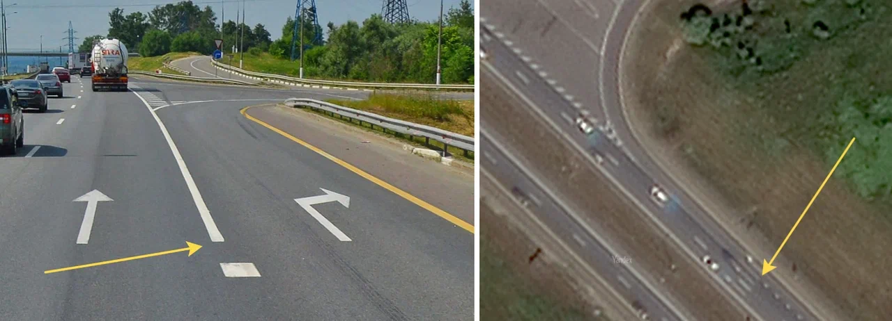
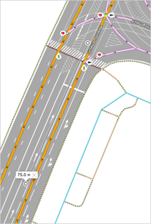
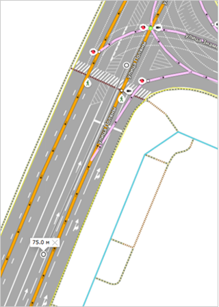
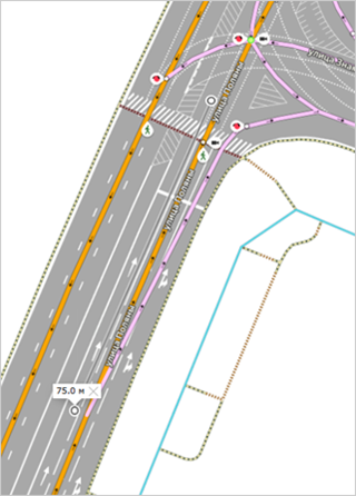
If there is no dedicated exit lane, you can draw the exit no more than 75 meters before the start of the solid line or safety island.
Example
In the image below, the yellow arrow indicates the starting point of the safety island and the white arrow indicates the point 75 meters away from the starting point of the safety island. The most correct and preferred option is to draw the exit from the red arrow (see rule 3.3.1.5.4.2), but you can also draw it anywhere between the red and white arrows.
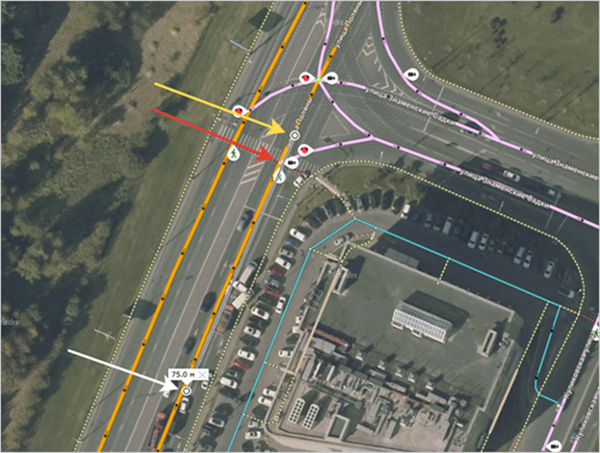
Preferred
Acceptable
Acceptable
The extended exit should not intersect with other roads that go along the way before the start of the exit itself: the exit should begin strictly after such roads.
If the exit is artificially extended, its geometry should decrease the angle to the main road gradually. There should be no additional curves on such an exit.
Example
Correct
Incorrect
-
3.3.1.5.4.4
-
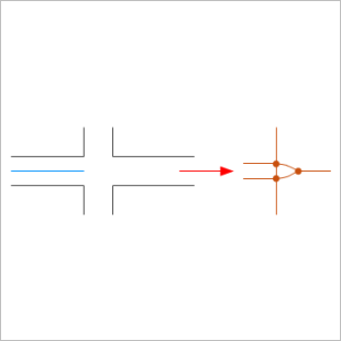
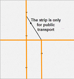
If extended 1.16.2 markings separate with-flow traffic lanes, the exits are drawn as a trapezoid, provided that there's no lane section specifically allocated for public transport between them.
Example
The image below shows an example of an incorrectly drawn exit:
If there is a section between the exits specifically allocated for public transport (and taxis if there are no additional signs), draw the exits according to the general rule (don't add an additional line for the public transport section):
Example
3.3.1.5.4.5
-
If the exits on a two-way road are marked by a traffic island with solid line markings that separate oncoming traffic, draw the intersection of the exits at the point where the traffic island ends, not at the point where the solid line markings end.
3.3.1.5.5
When drawing intersections with a combination of one- and two-lane roads, convergence of two-lane roads into one-lane roads within the intersection is prohibited:
|
Incorrect |
Incorrect |
|
|
|
3.3.1.5.5.1
-
At the intersection of two-way roads, we recommend converging a two-lane road into a one-lane road after the crossing of the road network sections (after the intersection). But you may also draw convergence before these sections cross (that is, before the intersection).
Alert
Make the convergence of a two-lane road into a one-lane one smooth(see point 3.3.1.2.4).
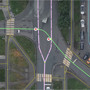
Note
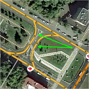
If a road section behind the intersection is intended only for public transport, draw it on the map and set its class to 7 (Roads of minimal significance):
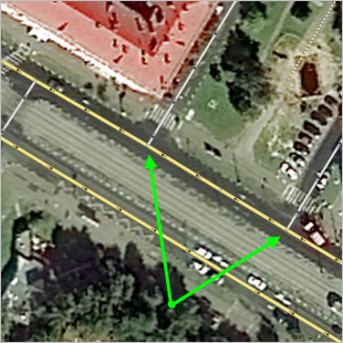
If two two-lane roads and one one-lane, one-way road approach an intersection, then the convergence of the two-lane road into one-lane is not drawn down the middle of the road, but rather as indicated in the drawing on the left (the green arrows indicate the permitted traffic directions):
3.3.1.5.5.2
-
If two two-lane roads (and one or two one-lane roads) approach an intersection, then we recommend converging these roads into a one-lane road after the intersection. But you may also do it before the intersection:
3.3.1.5.5.3
-
If a two-lane road forms a T-shaped intersection with a one-lane road, then the former will not converge into a one-lane road:
3.3.1.5.5.4
-
If the intersection has two-lane roads and barriers, then draw the intersection to reflect where vehicles can actually pass through:
3.3.1.6. Drawing rules for sidewalks, pedestrian paths, and bike paths
3.3.1.6.1
The Pedestrian paths class comprises the following:
-
Roads that are not wide enough for vehicles
-
Pedestrian paths
-
Sidewalks
-
Roads within parks and cemeteries
-
Pedestrian walkways across railway tracks and motorways
-
Pedestrian staircases, bridges, and tunnels
Note
When you draw pedestrian roads and sidewalks, you can use road color-coding to represent Pedestrian accessibility (in other words, use different colors to show whether or not a road is accessible to pedestrians).
Do not draw too many unpaved pedestrian roads (paths) on a restricted area (for example, in a single courtyard), even if they can be discerned from a satellite image. It is necessary to single out the key points among them (providing access to public service points, public transport stops, etc.) and draw only them.
Note
Significant pedestrian paths (such as Arbat St. in Moscow) are class 7 (Streets in localities)
; set the access as pedestrian-only for them.
3.3.1.6.1.1
-
Don't draw items that resemble sidewalks or pedestrian paths but do not function as such (for example, commercial passageways):
-
Narrow passages along roads that duplicate the route of the main sidewalk are also considered technical:
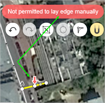
-
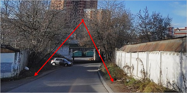
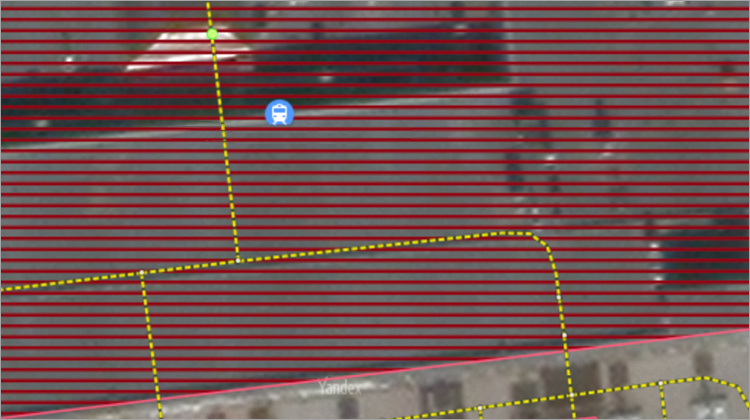
You also shouldn't draw individual sections of pedestrian paths if they're completely isolated from the rest of the network.
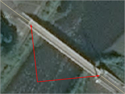
For example, the entrance to this bridge is blocked off by permanently closed gates, which is why you shouldn't draw the bridge's road section:
-
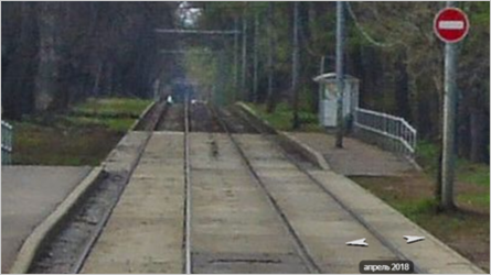
Do not draw tram tracks on paved roads that are not allowed for vehicles as separate lines:
3.3.1.6.1.2
-
Sidewalks, pedestrian and Bicycle paths are drawn on a conditional basis.
axial
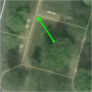
lines.If an areal item is inaccessible to cars and has no visible
axial
pedestrian path lines, it should be drawn along the shortest path and at right angles if possible. You can also draw additional pedestrian paths along the perimeter of the areal item.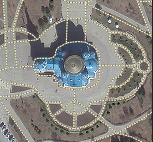
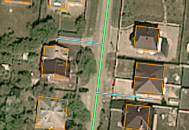
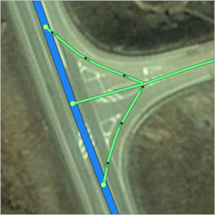
3.3.1.6.2
Lines representing pedestrian crosswalks, sidewalks, and pedestrian zones should form a connected network with the entire road network as a whole.
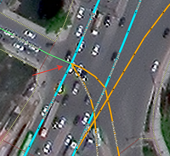
Networks of alleys and pedestrian roads running through parking lots and cemeteries should connect in the proper location to sidewalks and motorways that have the accessible to pedestrian attribute marked.
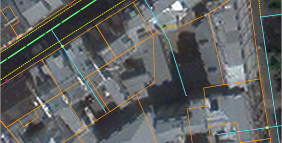
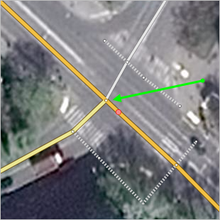
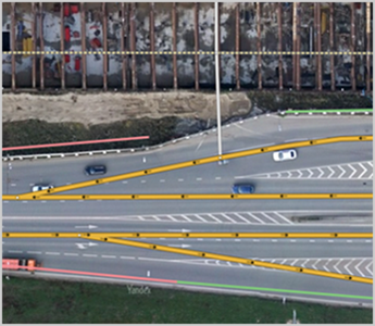
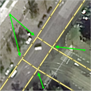
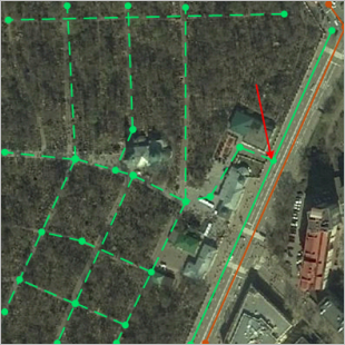
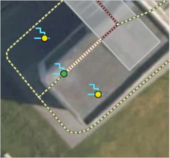
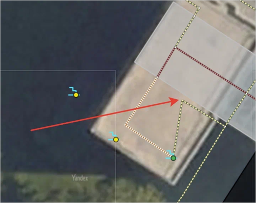
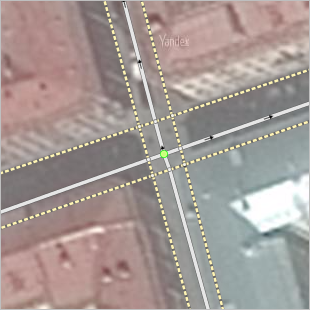
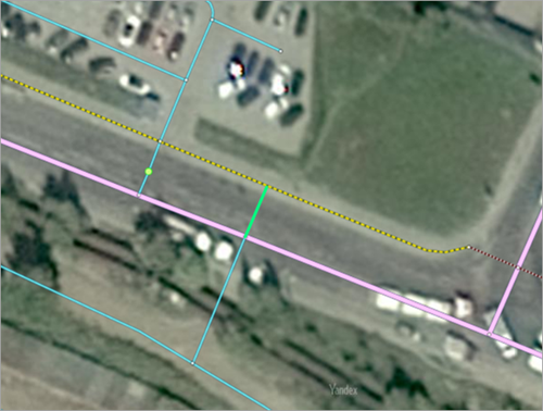
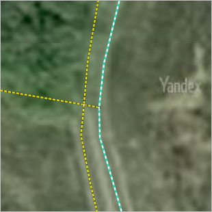
For example, the solid green line indicates a sidewalk in the drawing, the dotted line represents a network of pedestrian paths in a cemetery, and the brown line — a section of motorway. The red arrow indicates the point where they intersect. A fragment of the broader road graph is displayed on the drawing:
3.3.1.6.2.1
-
Fragments of the road network accessible to pedestrians might be disconnected from one another.
For example, the pedestrian roads on the island of Kronstadt near St. Petersburg form a network that pedestrians cannot reach from other areas of the city (they only connect to the A-118 freeway-ringroad).
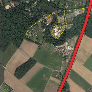
In similar situations do not artificially link the isolated sections of the road network available to pedestrians to each other, indicating accessibility to pedestrians where it is not available.
Exceptions to this rule are allowed in the situations described in 3.3.1.6.3.6.
3.3.1.6.2.2
-
For sports fields and playgrounds, you can draw main paths (passages) with no restricted entry even if they are not actually physically marked.
When drawing such paths, go around field/playground objects. Do not draw paths through goal posts or football
pitches
.Note
Mark such paths as not accessible to bicyclists.
3.3.1.6.2.3
-
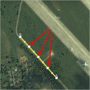
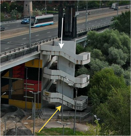
When drawing a spiral staircase, connect its start and end points as directly as possible, while still replicating the geometric characteristics of some of the staircase flights. Don't draw all of the staircase's actual spiral turns.
The start and end points of a spiral staircase are determined by its first and last steps.
Examples
-
The images below show the actual staircase as it appears in reality and its satellite view. The white arrows mark the point where the staircase steps end. The yellow arrows indicate the point where the staircase steps begin. Note that this point is not visible in the satellite image.
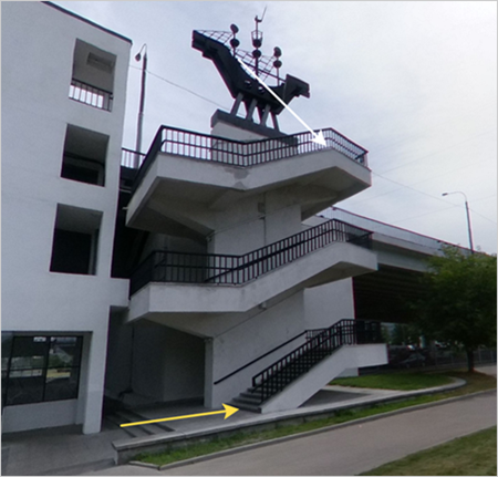
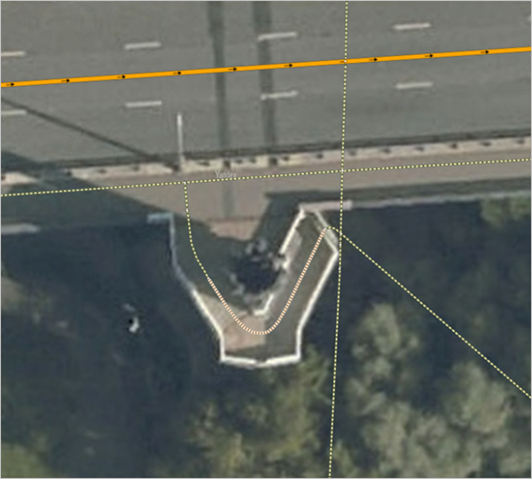
In this case, render the spiral staircase as a line connecting the white and yellow arrows. This line should take the shortest path between the start and end points while still reproducing a portion of the flight geometry.
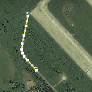
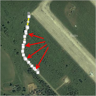
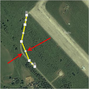
-
The images below show the actual staircase as it appears in reality and its satellite view. The white arrows mark the point where the staircase steps end. The yellow arrows indicate the point where the staircase steps begin. Note that this point is not visible in the satellite image.
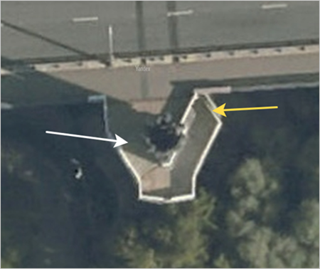
As in the previous example, you should render the spiral staircase as a line connecting the white and yellow arrows as directly as possible while still reproducing a portion of the flight geometry.
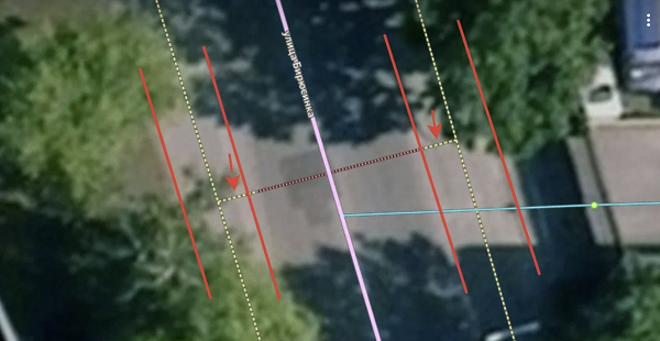
For certain spiral staircases that are drawn in areas with highly detailed roads, there are additional rules.
When the highly detailed roads layer is enabled, entry points are displayed on the backdrop for such staircases.
These points are calculated automatically, and the spiral staircase must begin at one of them.
Unless the beginning of the staircase has not been extended to the required point, all the points are displayed in red. A line is also drawn indicating which of the points the beginning of the staircase must be moved to.
After you move the beginning of the staircase to the required point, it turns green.
Keep in mind the following:
- The geometry of the staircase spiral turns must be preserved, but road sections may be shifted from the center of the staircase tread toward its edge.
- You can move the starting point of the staircase along the spiral turn to extend or shorten the staircase.
Examples
The rendering on the left is correct: an arrow indicates the actual starting point of the staircase, the geometry of the spiral turn is preserved, but the staircase is shortened.
The rendering on the right is incorrect: an arrow indicates the actual starting point of the staircase, the staircase is shortened and offset from the center of the tread, but only partially, and because of this the spiral geometry isn't preserved.
Correct
Incorrect
Aligning the beginning of the staircase with an entry point is desirable, but not mandatory. Changing the beginning of the staircase that is aligned with an entry point to a misaligned variant is an error.
-
3.3.1.6.3. Sidewalks
3.3.1.6.3.1
-
Draw sidewalks as separate roads if the sidewalk is separated from the roadway by a physical barrier (such as a lawn, chainlink fence, or other fence). Chainless posts between the road and the sidewalk are not considered physical barriers.
Draw sidewalks that are only separated from the road by the curb as separate roads running alongside roads of class 1-7:
Sidewalks along class 8 roads are drawn with a separate line provided that there's a perpendicular or angled parking between the sidewalk and the road.
You can draw a sidewalk as a separate line of the road network in places where pedestrians access the territory through a gate (in addition, mark the gate as an entry/exit restriction).
You can draw a separate line for the sidewalk in this case, but it's not mandatory.
3.3.1.6.3.2
-
The shoulder of a highway is not considered to be a sidewalk; do not draw it as a separate road.
If the shoulder of a road segment is accessible to pedestrians, then don't draw it as a sidewalk running along that segment, but rather add the accessible to pedestrian attribute to the applicable segment.
3.3.1.6.3.3
-
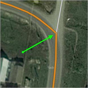
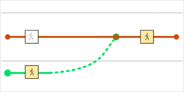
To ensure connectivity of the road network in areas where the pavement ends, but the further movement of pedestrians is possible on the side of the road, should smoothly join the line of the sidewalk and the road segment pedestrian road (in the picture the green dotted line):
3.3.1.6.3.3.1
-
Don't draw technical connections between pedestrian roads and sidewalks on freeways (class 1 roads). For example, the sidewalk line at a stop on the MKAD (Moscow ring road) ends on the map at the spot where the sidewalk physically ends:

3.3.1.6.3.4
-
If there are no pedestrian overpasses or pedestrian underpasses, as well as no signs or markings on the intersections (
zebras
), the pedestrian road passes through the intersection as an extension of the sidewalk line in the following cases:-
The roadway(s) of the intersected road has 3 traffic lanes or less.
-
The intersected road does not have a solid center line:
-
3.3.1.6.3.5
-
In places where a pedestrian path approaches a roadway, you can draw the intersection the following ways:
-
Along the pedestrian crosswalk (if there is one).
-
With no pedestrian crosswalk (if the intersecting motorway has no solid lane marker):
If the intersecting motorway has a solid lane marker, then you can draw the pedestrian road either as a separate road leading to the closest pedestrian crosswalk, or (if there is no road shoulder) you can draw it as a dead end:
-
3.3.1.6.3.6
-
If part of the road network accessible to pedestrians is isolated from the larger road network accessible to pedestrians (for example, industrial zone roads facing a street without a sidewalk and curb on one side), it is allowed to draw a pathway: a class 10 intersecting road accessible to pedestrians, which will connect the isolated section of the road network to the sidewalk.
In this case, the following conditions must be met:
- The pathway from the isolated section to the sidewalk does not cross a physical barrier (for example, a fence or lawn).
- Oncoming traffic lanes of roads with a pedestrian crossing are not divided by a median or one-way roads have three traffic lanes or less. Examples:
-
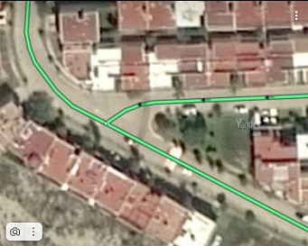
A pathway (green line) is drawn:
-
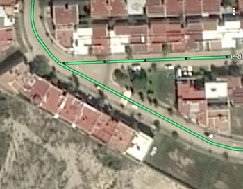
A pathway (red line) is not drawn because it would have crossed a physical barrier ( lawn):
-
A pathway (red line) is not drawn because it would have crossed a motorway with more than three lanes:
3.3.1.6.3.7
-
You can map roads located at different levels that provide a quick passage between the airport building and its infrastructure (such as a parking lot).
Roads inside and outside the building that go on any level except the first one must have a level different from 0 and connect to the main road network.
3.3.1.6.4. Pedestrian crosswalks
3.3.1.6.4.1
- Draw lines representing pedestrian crosswalks down the middle of the crosswalks themselves.
3.3.1.6.4.2
-
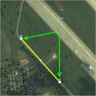
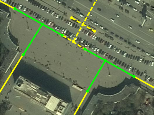
If the pedestrian crosswalk ends at a square that is accessible to pedestrians, then the points where the crossing ends and the entrance to the square begins are connected using segments of hypothetical pedestrian paths. Draw these paths at right angles from each other (if possible) and keep their use to a minimum.
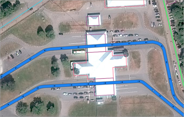
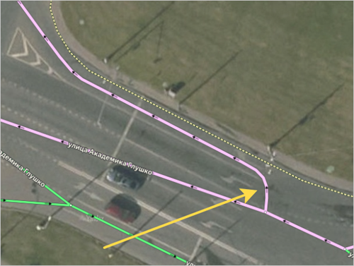
Pedestrian roads display as yellow lines in the drawing, underground crossings — yellow dotted lines, hypothetical connecting paths — green lines:
3.3.1.6.4.3
-
Lines for aboveground and underground pedestrian crosswalks lead to the point where the ascent/descent begins (if the ascent/descent includes section of level ground, simplify your drawing so that there are no more than two sections):
3.3.1.6.4.4
- Draw double pedestrian crosswalks (i.e. when two
zebra crossings
are located close to each other and you can only go in one direction on each of them) as a single line with the direction of traffic going both ways.
3.3.1.6.4.5
-
Only draw pedestrian crosswalks over railways in the following cases:
- If the crosswalk is aboveground
- If the crosswalk is underground
- If the crosswalk is clearly delineated at ground level (with barriers, a surface covering)
3.3.1.6.4.6
-
When drawing pedestrian crossings, you can either highlight short road sections that connect the crossing to the road network but aren't actually part of the crossing, or include them in the pedestrian crossing:
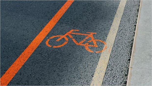
3.3.1.6.5. Bike paths
Only draw bike paths as separate roads if both of the following conditions are met:
- Using these paths doesn't violate traffic regulations.
- These roads are physically marked on the ground as bicycle paths and/or identified by road signs or road markings.
In all other cases it is enough to set the Accessible to bicyclists attribute for those sections of motorway (or pedestrian) roads.
If there is unrestricted access to a bike path from a pedestrian road/sidewalk, then the pedestrian roads connected to that sidewalk must lead to the bike path (and you should not change their accessibility marking):
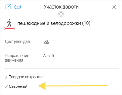
The seasonal attribute is used to label temporary bike paths in the data (editing is only available to employees).
This attribute is enabled for designated on-site bike paths that have a documented location and use span.
Alert
When drawing or editing the attributes of these bike paths, bike accessibility on nearby roads doesn't change and is set in accordance with the general rules for attributing similar items.
3.3.1.6.6
If a pedestrian road passes through the interior of a building, you should only draw the road if the building it passes through is a security checkpoint leading to a restricted area that belongs to an organization.
For example:
3.3.1.6.7
Approaches to ticketing halls, turnstile pavilions, turnstile lines, and station doors (station entrance points) that connect rapid transit stations with underground and aboveground passage territories at their point of contact may be mapped as additional sections of pedestrian roads.
Examples
Alert
These items are mapped only by the employees who work with the Transport layer.
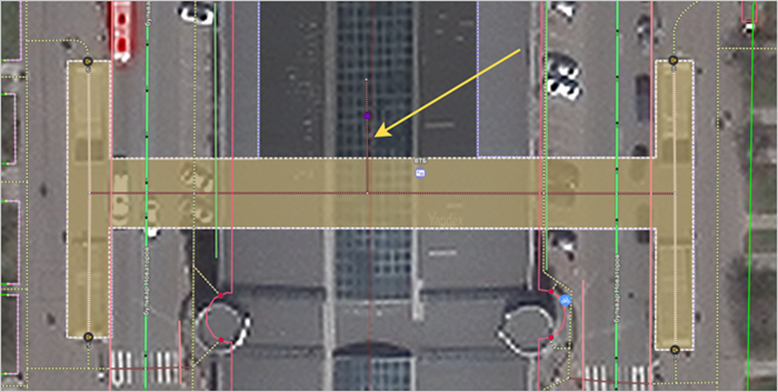
Pedestrian roads mark branches off the main passage sections at the station entrance. Additional sections created are typically 5–10 meters long.
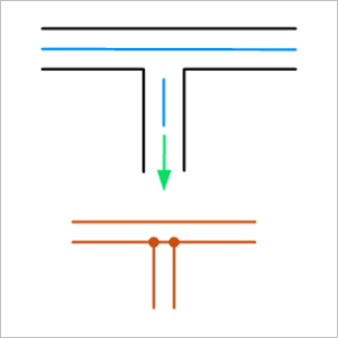
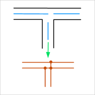
Branches may be drawn either perpendicular to the main passage sections (Figure 1) or parallel to the platform (Figure 2).
|
Figure 1 |
Figure 2 |
|
|
|
The attributes of the branch section must match the attributes of the main road.
3.3.1.7. Rules for drawing seasonal roads
Seasonal roads include ferry and ice crossings, and winter roads.
Due to the complete or partial absence of seasonal roads in satellite images, draw them based on your personal knowledge of the crossing's location and official information confirming their existence and indicating the points of departure and destination.
3.3.1.7.1
For ferry crossings, set the ferry crossing
value for the Type of structure attribute.
For ice crossings, set the "ice crossing" value for the "Type of structure" attribute.
For winter roads, leave the "Type of structure" attribute unfilled (value "None").
Note
If a section of the road network is included in both ferry and ice crossings at the same time, set the value of the "Type of structure" attribute as "ferry crossing" when the ferry crossing opens and until the ice crossing opens. Set the "ice crossing" value when the ice crossing opens and until the ferry crossing opens.
3.3.1.7.2
For named seasonal roads, an official
name can be indicated. In this case don't set the caption for the map
. See point 3.3.3.3.3.4. Highways without a number, but with a proper name.
3.3.1.7.3
If ice and ferry crossings operate seasonally on the same route (the starting and ending points of the ice and ferry crossings are the same), or their routes are in close proximity to one another, then these items should include the same sections of the road network.
3.3.1.7.4
Don't draw pedestrian paths that are formed and available only in winter.
For example, ski trails and paths that pass through reservoirs.